Introduction
This guide shows how to assemble and install all generations of APS adjusters. Even if the outer ring of your APS adjuster looks different than the version shown here, this guide still applies to your system as well.
-
-
Start with installing detent ring on the crank spindle base. The spring tang should be facing out from the arm and the 3 keys on the detent ring should slide into the corresponding groves on the crank.
-
The black rubberized side of the detent ring should be flush against the base of the spindle with the shinny silver portion and spring tang facing away from the arm.
-
-
-
lightly grease the APS adjuster.
-
Thread the inner APS ring into the larger APS ring so the two parts are flush as can be.
-
-
-
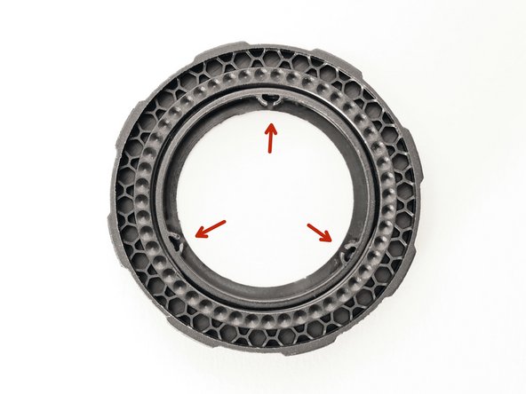
Note and Inspect prongs on inner ring. These are critical for APS function.
-
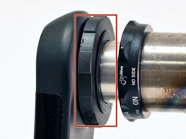
Line up the 3 prongs on APS with 3 slots on crank spindle base and press APS adjuster onto spindle base.
-
Notches on the outer ring should press up against the spring tang.
-
Make sure APS is fully seated on base of spindle during the crank install process. Should the APS slide out of the keyways and get compressed during the tightening process, the keys will get crushed and APS rendered inoperable.
-
-
-
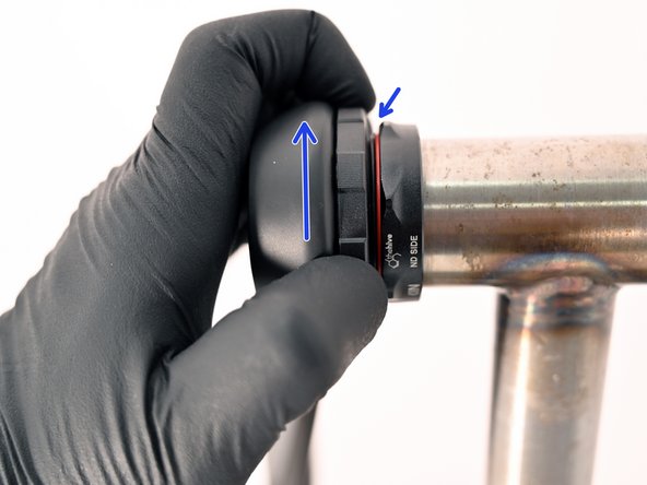
Adjust bearing preload by turning the APS adjuster counter-clockwise
-
note how the inner portion of the adjuster moves and closes the gap between the adjuster and the bearing
-
Hand tighten the APS adjuster until no side to side play is felt in the spindle
-
This can be double checked by squeezing the non-drive arm against the bikes chainstay
-